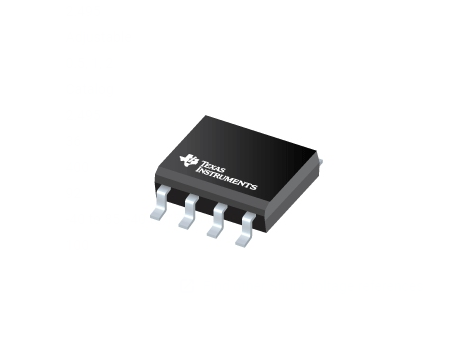
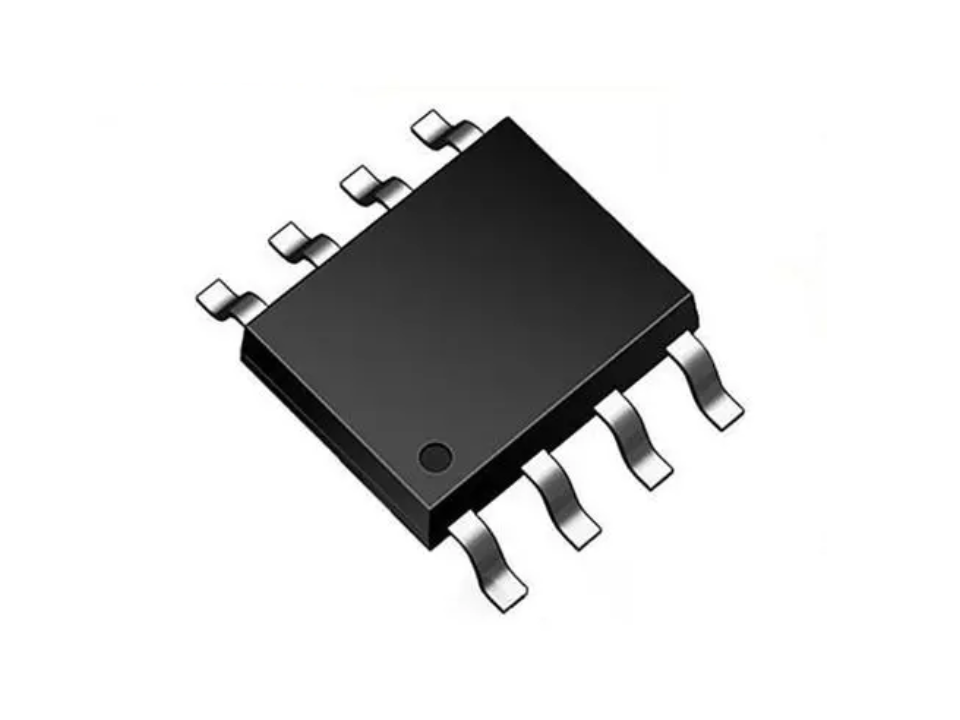
The SN65HVD230, SN65HVD231, and SN65HVD232 controller area network (CAN) transceivers are compatible to the specifications of the ISO 11898-2 High Speed CAN Physical Layer standard (transceiver). These devices are designed for data rates up to 1 megabit per second (Mbps), and include many protection features providing device and CAN network robustness. The SN65HVD23x transceivers are designed for use with the Texas Instruments 3.3 V µPs, MCUs and DSPs with CAN controllers, or with equivalent protocol controller devices. The devices are intended for use in applications employing the CAN serial communication physical layer in accordance with the ISO 11898 standard.
Designed for operation in especially harsh environments, these devices feature cross wire protection, loss of ground and overvoltage protection, overtemperature protection, as well as wide common mode range of operation.
The CAN transceiver is the CAN physical layer and interfaces the single ended host CAN protocol controller with the differential CAN bus found in industrial, building automation, and automotive applications. These devices operate over a -2 V to 7 V common mode range on the bus, and can withstand common mode transients of ±25 V.
The RS pin (pin 8) on the SN65HVD230 and SN65HVD231 provides three different modes of operation: high speed mode, slope control mode, and low-power mode. The high speed mode of operation is selected by connecting the RS pin to ground, allowing the transmitter output transistors to switch on and off as fast as possible with no limitation on the rise and fall slopes. The rise and fall slopes can also be adjusted by connecting a resistor in series between the RS pin and ground. The slope will be proportional to the pin’s output current. With a resistor value of 10 k? the device will have a slew rate of ~15 V/µs, and with a resistor value of 100 k? the device will have a slew rate of ~2 V/µs. See Application Information for more information.
The SN65HVD230 enters a low current standby mode (listen only) during which the driver is switched off and the receiver remains active if a high logic level is applied to the RS pin. This mode provides a lower power consumption mode than normal mode while still allowing the CAN controller to monitor the bus for activity indicating it should return the transceiver to normal mode or slope control mode. The host controller (MCU, DSP) returns the device to a transmitting mode (high speed or slope control) when it wants to transmit a message to the bus or if during standby mode it received bus traffic indicating the need to once again be ready to transmit.
The difference between the SN65HVD230 and the SN65HVD231 is that both the driver and the receiver are switched off in the SN65HVD231 when a high logic level is applied to the RS pin. In this sleep mode the device will not be able to transmit messages to the bus or receive messages from the bus. The device will remain in sleep mode until it is reactivated by applying a low logic level on the RS pin.


 | 0 订单数量
 顺丰速运 (https://www.sf-express.com/)
 圆通快递 (https://www.yto.net.cn/)
 中通快递 (https://www.zto.com/)
 顺丰速运 (https://www.sf-express.com/)港澳台
 无需物流 (线下配送)
 规格书
规格书
